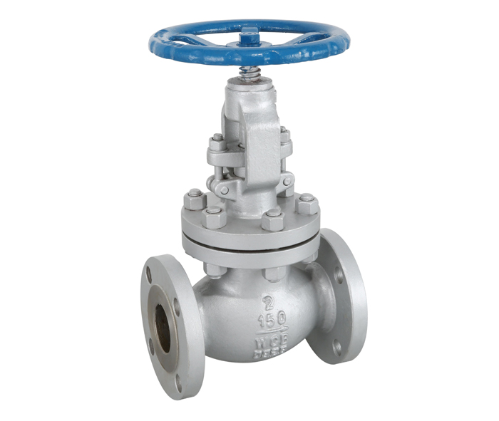
American Standard stop valve
National Advisory Hotline
+86-18752587151Product description
J41H/Y/W-16~100C,P,R
characteristic:
Streamlined, rising pole with support
Middle flange bolt connection
Looper connecting disc
Lifting valve stem and hand wheel
Integrated support and valve cover
Bevel gear operation options
Standard flange connection
Product specification
Design specification structural length connecting flange test and inspection pressure temperature product identification supply specification
API600 ANSI B16.10 ANSI B16.5 API598 ANSI B16.34 MSS SP-25 API600
BS 5160 BS 5160
Material list
Part name part material
Body / bonnet a216-wcb a217-wc6 a352-lcb a351-cf8m
Disc A105 a182-f11 a182-f304 a182-f316
Valve stem a182-f6a a182-f11 a182-f6a a182-f316
Filler flexible graphite PTFE / PTFE
Gasket 18-8 flexible graphite
Bolt a193-b7 a193-b7 a193-b7m a193-b8
Applicable temperature: - 29 ~ 425 ℃ - 29 ~ 550 ℃ - 46 ~ 350 ℃ - 40 ~ 200 ℃
Applicable media: water, oil, steam, propane, ethylene and nitric acid
Main outline and connection dimensions
American Standard 150Lb
NPS | DN | L | D | D1 | D2 | b | f | z-φd |
1/2 | 15 | 108 | 90 | 60.3 | 34.9 | 11.6 | 2 | 4-15.9 |
3/4 | 20 | 117 | 100 | 69.9 | 42.9 | 13.2 | 2 | 4-15.9 |
1 | 25 | 127 | 110 | 79.4 | 50.8 | 14.7 | 2 | 4-15.9 |
11/4 | 32 | 140 | 115 | 88.9 | 63.5 | 16.3 | 2 | 4-15.9 |
11/2 | 40 | 165 | 125 | 98.4 | 73 | 17.9 | 2 | 4-15.9 |
2 | 50 | 203 | 150 | 120.7 | 92.1 | 19.5 | 2 | 4-19 |
21/2 | 65 | 216 | 180 | 139.7 | 104.8 | 22.7 | 2 | 4-19 |
3 | 80 | 241 | 190 | 152.4 | 127 | 24.3 | 2 | 4-19 |
4 | 100 | 292 | 230 | 190.5 | 157.2 | 24.3 | 2 | 8-19 |
5 | 125 | 356 | 255 | 215.9 | 185.7 | 24.3 | 2 | 8-22.2 |
6 | 150 | 406 | 280 | 241.3 | 215.9 | 25.9 | 2 | 8-22.2 |
8 | 200 | 495 | 345 | 298.5 | 269.9 | 29 | 2 | 8-22.2 |
10 | 250 | 622 | 405 | 362 | 323.8 | 30.6 | 2 | 12-25.4 |
12 | 300 | 698 | 485 | 431.8 | 381 | 32.2 | 2 | 12-25.4 |
14 | 350 | 787 | 535 | 476.3 | 412.8 | 35.4 | 2 | 16-25.4 |
16 | 400 | 914 | 595 | 539.8 | 469.9 | 37 | 2 | 16-28.6 |
18 | 450 | 978 | 635 | 577.9 | 533.4 | 40.1 | 2 | 16-31.8 |
20 | 500 | 978 | 700 | 635 | 584.2 | 43.3 | 2 | 20-31.8 |
24 | 600 | 1295 | 815 | 749.3 | 692.2 | 48.1 | 2 | 20-34.9 |
American Standard stop valve
J41/H/Y/W-150~600LB
Main outline and connection dimensions
American Standard 300lb
NPS | DN | L | D | D1 | D2 | b | f | z-φd |
1/2 | 15 | 152 | 95 | 66.7 | 34.9 | 14.7 | 2 | 4-15.9 |
3/4 | 20 | 178 | 115 | 82.6 | 42.9 | 16.3 | 2 | 4-19 |
1 | 25 | 203 | 125 | 88.9 | 50.8 | 17.9 | 2 | 4-19 |
11/4 | 32 | 216 | 135 | 98.4 | 63.5 | 19.5 | 2 | 4-19 |
11/2 | 40 | 229 | 155 | 114.3 | 73 | 21.1 | 2 | 4-22.2 |
2 | 50 | 267 | 165 | 127 | 92.1 | 22.7 | 2 | 8-19 |
21/2 | 65 | 292 | 190 | 149.2 | 104.8 | 25.9 | 2 | 8-22.2 |
3 | 80 | 318 | 210 | 168.3 | 127 | 29 | 2 | 8-22.2 |
4 | 100 | 356 | 255 | 200 | 157.2 | 32.2 | 2 | 8-22.2 |
5 | 125 | 400 | 280 | 235 | 185.7 | 35.4 | 2 | 8-22.2 |
6 | 150 | 444 | 320 | 269.9 | 215.9 | 37 | 2 | 12-22.2 |
8 | 200 | 559 | 380 | 330.2 | 269.9 | 41.7 | 2 | 12-25.4 |
10 | 250 | 622 | 445 | 387.4 | 323.8 | 48.1 | 2 | 16-28.6 |
12 | 300 | 711 | 520 | 450.8 | 381 | 51.3 | 2 | 16-31.8 |
14 | 350 | 585 | 514.5 | 412.8 | 54.4 | 2 | 20-31.8 | |
16 | 400 | 650 | 571.5 | 469.9 | 57.6 | 2 | 20-34.9 | |
18 | 450 | 710 | 628.6 | 533.4 | 60.8 | 2 | 24-34.9 | |
20 | 500 | 775 | 685.8 | 584.2 | 64 | 2 | 24-34.9 | |
24 | 600 | 915 | 812.8 | 692.2 | 70.3 | 2 | 24-41.3 |
American Standard 600LB
NPS | DN | L | D | D1 | D2 | b | f | z-φd |
1/2 | 15 | 165 | 95 | 66.7 | 34.9 | 21.3 | 7 | 4-15.9 |
3/4 | 20 | 190 | 115 | 82.6 | 22.9 | 22.9 | 7 | 4-19 |
1 | 25 | 216 | 125 | 88.9 | 50.8 | 24.5 | 7 | 4-19 |
11/4 | 32 | 229 | 135 | 98.4 | 63.5 | 27.7 | 7 | 4-19 |
11/2 | 40 | 241 | 155 | 114.3 | 73 | 29.3 | 7 | 4-22.2 |
2 | 50 | 292 | 165 | 127 | 92.1 | 32.4 | 7 | 8-19 |
21/2 | 65 | 330 | 190 | 149.2 | 104.8 | 35.6 | 7 | 8-22.2 |
3 | 80 | 356 | 210 | 168.3 | 127 | 38.8 | 7 | 8-22.2 |
4 | 100 | 432 | 275 | 215.9 | 157.2 | 45.1 | 7 | 8-25.4 |
5 | 125 | 508 | 330 | 226.7 | 185.7 | 51.5 | 7 | 8-28.6 |
6 | 150 | 559 | 355 | 292.1 | 215.9 | 54.7 | 7 | 12-28.6 |
8 | 200 | 660 | 420 | 349.2 | 269.9 | 62.6 | 7 | 12-31.8 |
10 | 250 | 787 | 510 | 431.8 | 323.8 | 70.5 | 7 | 16-34.9 |
12 | 300 | 838 | 560 | 489 | 381 | 76.7 | 7 | 20-34.9 |
14 | 350 | 889 | 605 | 527 | 412.8 | 76.9 | 7 | 20-38.1 |
16 | 400 | 991 | 685 | 603.2 | 469.9 | 83.2 | 7 | 20-413 |
18 | 450 | 1092 | 745 | 654 | 533.4 | 89.6 | 7 | 20-44.5 |
20 | 500 | 1194 | 815 | 723.9 | 584.2 | 95.9 | 7 | 24-44.5 |
24 | 600 | 1397 | 940 | 838.2 | 692.2 | 108.6 | 7 | 24-50.8 |
Recommended news
-
What are the common faults of valve special motors
2021-07-22 -
Principles of valve selection in the petroleum and ch…
2021-07-22 -
Application and principle of speed control valve
2021-07-22 -
Types and working principles of gate valves
2021-07-22 -
Do you know everything about the installation of chec…
2021-07-22 -
Why is the use of gate valves forbidden in oxygen pip…
2021-07-22 -
Introduce the working principle of high pressure angl…
2021-07-22 -
Flat gate valve use structure description characteris…
2021-07-22

